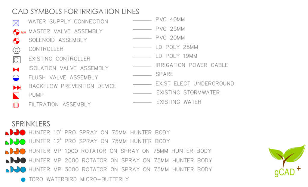
It is helpful to have a set of irrigation symbols (blocks) available when designing irrigation layouts for gardens and larger spaces. Download this palette from a link on this page and get symbols for water connections, controllers, solenoid valves, irrigation lines, sprinklers, etc.

Tip: The symbols here are designed for use in the metric environment where the base drawing unit is mm.
The palette includes symbols to indicate the position of the water source, master valve assembly, solenoid valves, typical controllers and a range of rotators and spray heads.
Each symbol has been drawn on its own layer, L-IRRIG, to facilitate easy insertion using the BLOCKS command. The base point is set in the centre of the symbol.
Tip: Once the symbols have been placed and the design finalized, use the block extraction tools on the gCADPlus drop-down menu to extract quantities
Each irrigation line has been placed on its layer as an additional benefit. For example, a 25mm PVC piping line has been placed on a separate layer L-IRRIG-PVC-25MM. This allows the isolation of that layer and subsequent extraction of the required piping length.
Tip: Layer naming conventions follow those published by the American Institute of Architects for designers using AutoCAD software.
The figure below shows a typical layout created using this symbol set.

![]() This small movie shows how to download a palette of extra symbols to gCADPlus and use them in a developing design.
This small movie shows how to download a palette of extra symbols to gCADPlus and use them in a developing design.
Here is a link to symbols more suited to larger-scale open-space irrigation projects.