|
SketchUp Tools |
||||||||||||||||||
|
SketchUp provides a series of additional tools which can assist in editing your models. These can be activated from the Tools drop down menu and we will cover the use of some of these tools in this module.
Activating the Edit toolbarIt is well worth activating and displaying the modification palette (toolbar) when you find the need to use these more advanced editing tools in the SketchUp environment.
More tools It is important to keep in mind that editing tools can be located on the standard toolbar, the Edit drop down menu and the Edit toolbar. Let's look at some more of these.
Eraser (adapted from the Help file)Use the Eraser Tool to delete entities. The Eraser Tool can also be used to hide and soften edges. Activate the Eraser Tool from the Principal toolbar, or by selecting Eraser from the Tools menu. Keyboard Shortcut: E Erasing Entities As mentioned previously, the Eraser Tool is used to erase entities in the drawing area. Note, the Eraser Tool does not allow you to erase faces (faces are erased after their bounding edges are erased). To erase entities:
If you accidentally select geometry you do not wish to delete, press the ESC key to cancel the erase operation before it deletes your selection.
Hiding Lines Press and hold the Shift key and use the Eraser Tool to hide lines (instead of erasing lines). Softening/Unsoftening Edges Press and hold the Ctrl key to soften/smooth edges (instead of erasing entities). Press and hold the Shift and Ctrl keys simultaneously to unsoften/unsmooth edges. Paint BucketUse the Paint Bucket Tool to assign materials and colors to entities in your model. You can use it to paint individual entities, fill a number of connected faces, or replace a material with another throughout your model. Activate the Paint Bucket Tool from the Principal toolbar, or by choosing Paint Bucket from the Tools menu. Keyboard Shortcut: B Applying Materials Ensure you are using either the Shaded or Shaded with Textures display setting so that you can see materials as they are applied to your model (Window > Display Settings > Shaded or Shaded with Textures). To apply materials:
Face Painting Rules There are several face painting rules that apply when painting multiple faces or edges at the same time. These rules follow:
Fill Options The Paint Bucket Tool can be used with one or more keyboard modifiers to perform various painting operations. Element Fill The Paint Bucket Tool normally operates by filling in faces as you click on them. As mentioned previously, entities selected with the Select Tool can be painted with a single click of the Paint Bucket Tool. Adjacent Fill Press and hold the Ctrl key while clicking on a face with the Paint Bucket Tool to fill that face and any adjacent (connected) face with the same material. The face you click on and the adjacent face must have the same material prior to performing this operation.
Replace Press and hold the Shift key prior to clicking on a face with the Paint Bucket Tool to apply a material to every face, with the same material in the current context, with the new material.
Adjacent Replace Press and hold both the Shift and the Ctrl keys simultaneously while painting to only replace the material on the face within the confines of geometry that is physically connected to that face.
Sampling a Material Press and hold the Alt key to change from the Paint Bucket Tool to a Sample Tool for sampling materials within your model. The cursor will change to an eye dropper. Click on the face whose material you want to sample. Release the Alt key to return to the Paint Bucket Tool. Paint the sampled material on a face.
Painting Groups and Components Materials can be painted on entire Group entities or Component entities or to the individual entities within the Group or Component. To assign materials to an entire Group or Component:
MoveUse the Move Tool to move, stretch and copy geometry. This tool can also be used to rotate components and groups. Activate the Move Tool using the Modification toolbar or the Tools menu. Keyboard Shortcut: M Moving a Single Entity You can activate the Move Tool when nothing is selected to select a single entity to move. The selection click point becomes the base point for the move operation. To select and move a single entity:
Moving Several Entities You can preselect several entities to move prior to performing a move operation. To preselect and move entities:
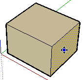
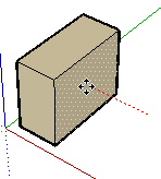
Moving by Inference The Move Tool uses SketchUp's sophisticated geometric inference engine to help you place entities in 3D space. The inference decisions, made by the inference engine, are displayed in the drawing area as inference lines and inference points. These lines and points show precise alignment between the move operation and the geometry of your model. Refer to the inference engine topic for additional information. Locking a Move to the Current Inference Direction Press and hold the Shift key, while the move you are performing is the specific colour of an axis, to lock move operation to that axis. Locking a Line to a Specific Inference Direction Press and hold either the up arrow, left arrow, or right arrow keys, where up arrow equals blue, left arrow equals green, and right arrow equals red, while moving to lock the move to a specific axis. Moving Groups and Components If a component is glued to a face, the component will stay in the plane of that face when moved unless it is unglued. Copies of a glued component will also be glued to the originating plane. Stretching Geometry When you move an element that is interconnected with others, SketchUp will stretch geometry as necessary. You can move points, edges, and faces in this manner. For example, the following Face entity can be moved back in the negative red direction or up in the positive blue direction:
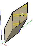
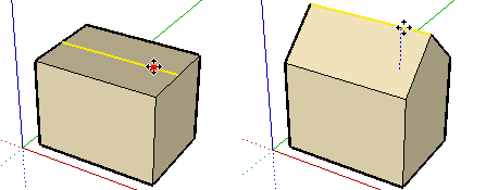
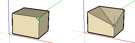
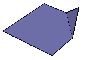
You can also move single line segments to stretch an object. In the following example, a line is selected and moved up in the blue direction to form a sloped roof.
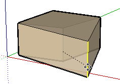
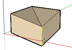
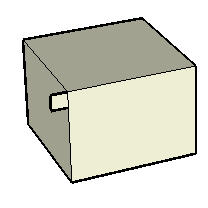
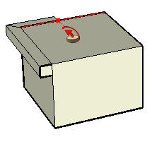
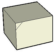
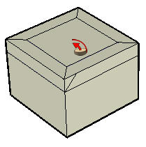
Moving/Stretching With Autofold SketchUp will Autofold faces automatically when a move or stretch operation will create non-planar faces. For example, clicking on the corner of a box with the move tool and move down in the blue direction causes SketchUp to create a fold line along the box's top face..
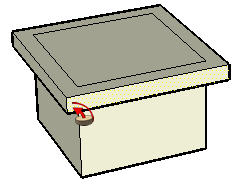
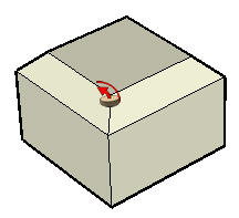
Forcing Autofold Behavior There are times when SketchUp constrains an operation in favor of keeping all faces planar and not creating additional fold lines. For example, clicking on the edge of a box with the move tool only allows you to move the edge in a horizontal direction (red and green), but not vertically (blue). You can override this behavior by pressing and releasing the Alt key before performing the move operation. This key sequence enables Autofold allowing geometry to move freely in any direction.
Making Copies As mentioned previously, the Move Tool can be used to make copies of entities within your model. To make copies of an entity using the Move Tool:
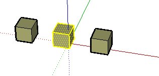
Creating Multiple Copies (Linear Arrays) The Move Tool can also be used to create arrays, or a series of copies of geometry. To create multiple copies of one or more entities:
Creating Copies at an Equal Distance Apart You can divide the distance between the copy and the original by typing in a divisor value. For example, typing 5/ (or /5) will create five copies evenly distributed between the original and the first copy. You can keep typing in distances and multipliers until you perform another operation.
Specifying Precise Move Values The VCB at the bottom right corner of the SketchUp window displays the length of the move operation (displacement) in the default units, as specified under the Units panel of the Model Info dialog box, while moving, copying, or stretching entities. In addition to creating arrays, you can also specify an exact displacement or a relative or absolute 3D coordinate for the finishing point during, or immediately after, a move operation. Entering a Displacement Value You can specify a new displacement length during or directly following a move operation. To enter a displacement value during a move operation:
Entering a 3D Coordinate SketchUp can move your entities to exact (using []) or relative (using <>) coordinates in 3D space. To enter a 3D coordinate during a move operation:
Global Coordinates: [x, y, z] of the current Sketch Axes:
Relative Coordinates: <x, y, z> relative to the start point:
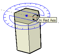
RotateUse the Rotate Tool to rotate, stretch, distort, or copy entities along a rounded path. Activate the Rotate Tool from either the Modification toolbar or the Tools menu. Keyboard Shortcut: Q Rotating Geometry You can rotate geometry in three different planes in a 3D environment. To rotate geometry using the Rotate Tool:
Rotational Stretching with Auto-Fold The Rotate Tool can also be used to stretch geometry by selecting and rotating a portion of the geometry. Any rotational movement that would cause a face to twist in on itself or otherwise become non-planar will activate SketchUp's Auto-Fold feature.
Making Copies The Rotate Tool can be used to make rotated copies of entities within your model. To make copies of an entity using the Rotate Tool:
Creating Multiple Copies (Radial Arrays) The Rotate Tool can also be used to create radial arrays, or a series of copies around a rotate point. To create a radial array.
.
Creating Copies at an Equal Distance Apart You can divide the distance between the copy and the original by typing in a divisor value in the VCB. For example, typing 5/ (or /5) will create five copies evenly distributed between the original and the first copy. You can enter distances and multipliers until you perform another operation. Folding Along an Axis of Rotation You can fold geometry by setting the protractor along an edge that will act like a fold line and then folding geometry at that line. To fold geometry along an axis of rotation:
Specifying Precise Angular Values The degree of rotation you have indicated appears in angular degrees in the VCB while rotating. You can also manually enter in angular rotation or slope values directly into the VCB while rotating geometry. Entering an Angular Rotation Value To specify an exact angle in degrees, type a decimal value into the VCB while rotating the cursor around the protractor. For example, typing in 34.1 will give you an exact 34.1 degree angle. Negative values will move angle in a counter-clockwise direction. You can specify an exact angular value either during or immediately after your rotation operation. Entering a Slope Value To specify a new angle as a slope, type in the two values separated by a colon in the VCB, such as 8:12. Negative values will move angle in a counter-clockwise direction. You can specify an exact angular value either during or immediately after your rotation operation. Locking the Rotate Tool to its Current Orientation Press and hold the Shift key, before you click on an entity, to lock the operation to that orientation. ScaleUse the Scale Tool to resize and stretch portions of geometry relative to other entities in your model. Activate the Scale Tool from the Modification toolbar or the Tools menu. Keyboard Shortcut:S
Scaling Geometry
Scaling Auto-Folding Geometry SketchUp's Auto-fold feature works automatically with all Scale operations. SketchUp will create folding lines as necessary to maintain planar faces. Scaling a 2D Surface or Image Entity Two-dimensional surfaces and Image entities can be scaled just as easily as three-dimensional geometry. The Scale Tool's bounding box contains nine scaling grips when scaling a 2D face. These operate in a similar manner to the grips in a 3D bounding box, and also work with the Ctrl and Shift modifiers. The bounding box is a 2D rectangle when scaling a single 2D surface that lies in the red-green plane. The bounding box will be a 3D volume if the surface to be scaled is out of plane with the current red-green plane. You can ensure a 2D scale by aligning the Drawing Axes to a surface prior to scaling. Scaling Components Scaling a Component entity scales the individual instance. All other instances of the component will retain their individual scales. This feature allows you to have many differently scaled versions of the same component in your model. Scale operations within a component's context (such as scaling a Line entity within a component) affects the component definition and, therefore, all instances of the component will be scaled to match (all instances of the same Line entity in all component instances). Scaling Grip Types Upon activation, the Scale Tool displays all the grips you may use. Any grips hidden behind geometry will become visible whenever touched by the mouse cursor, and remain fully operable. Turn on X-ray Transparency mode to reveal any hidden grips. The Scale Tool allows you to perform both uniform scaling and nonuniform scaling (stretching operations). The scaling grip that is used dictates the type of scaling you perform.
Corner Grips Corner grips scale the selected geometry from the opposite corner. The default behavior is a uniform scale such that the proportions remain intact and a single scale factor or dimension is displayed in the VCB. Edge Grips Edge grips scale the selected geometry from the opposite edge by two dimensions simultaneously. The default behavior is a nonuniform scale, meaning that the proportions of the object will change. The VCB displays two values separated by a comma. Face Grips Face grips scale the selected geometry from the opposite face in only one dimension. The default behavior is a nonuniform scale, meaning that the proportions of the object will change. The VCB displays and accepts a single value. Scaling About the Geometry Center The Scale Tool allows you to scale outward from geometry's center point. Hold down the Ctrl key at any time during a scale operation to display the geometry's center point, click on any of the other scaling grips, and drag outward or inward to scale accordingly. Scaling Uniformly You might need to maintain the uniformity of geometry as it is being scaled, despite performing nonuniform scaling. The Shift key toggles to uniform scaling operation (from a nonuniform scaling operation) and to nonuniform scaling operation (from a uniform scaling operation).
Controlling Scaling Direction With The Axis Tool You can precisely control the direction of scaling by first repositioning the drawing axes with the Axes Tool. The Scale Tool will use the new red, green, and blue directions to orient itself, and control grip direction, after the axes are repositioned.
Specifying Precise Scale Values The VCB at the bottom right corner of the SketchUp window displays the axis dimensions that are being scaled, and the value of the scale itself, in the default units (as specified under the Units panel of the Model Info dialog box) during a scaling operation. Type a scale value into the VCB to directly scale geometry during or immediately after a scaling operation. Entering a Scale Multiplier Value You can specify a new dimensional length value during or directly following an scaling operation. To enter a dimensional length value during a scaling operation:
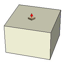
Mirroring Geometry using the Scale Tool The Scale Tool can also be used to mirror geometry by pulling a grip towards and then beyond the point about which you are scaling. This operation allows you to pull geometry inside out. Note that the grips snap to certain negative values (such as -1, -1.5, and -2) just as they do in the positive direction. You can force a mirror by typing in a negative value or dimension. Entering Multiple Scale Values The VCB always indicates the scaling factors associated with a particular operation. A 1D scaling operation requires one value. A 2D scaling operation requires two values, separated by a comma. A Uniform 3D scaling operation requires only one value whereas a Non Uniform 3D scaling operation requires three values, each separated by a comma. You'll notice that during the scale operation, a dashed line appears between the scaling point and the grip you've selected. Entering a single value or distance in the VCB tells SketchUp adjust the anchor to grip distance to be that scale value or distance, regardless of which mode (1D, 2D, 3D) is active. When scaling in multiple directions, typing in multiple values separated by commas will resize the object(s) based on the entire bounding box dimension(s), not the objects individually. (To scale objects based on a particular edge or known distance, you can use the Tape Measure Tool.) Push PullUse the Push/Pull Tool to push and pull Face entities to add volume to or subtract volume from your models. You can use push/pull to create volume out of any face type, including circular, rectangular, and abstract faces. Activate the Push/Pull Tool from either the Modification toolbar or the Tools menu. Keyboard Shortcut: P
Creating a Volume Push/Pull Tool is used to expand or decrease the volume of geometry in your models. To push or pull faces:
Repeating a Push/Pull Operation Double-clicking on another face immediately after a push/pull operation will automatically apply another push/pull operation, of the same amount, to the other face.
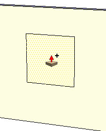
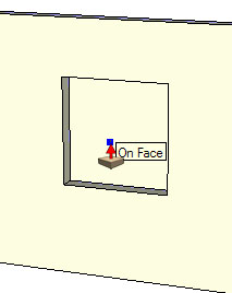
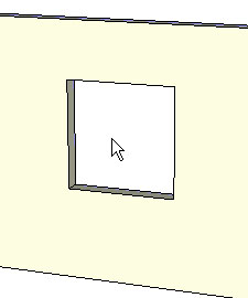
Creating Voids Push/pull will implode the shape into the volume and toward the back face of the volume when you use push/pull on a shape that is part of another volume. SketchUp will subtract the shape and create a 3D void if the shape is pushed completely out of the back of the volume as in the following example.
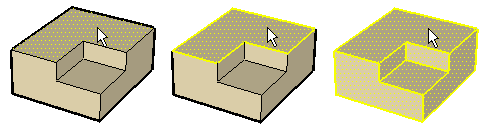
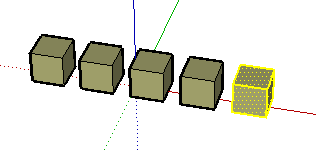
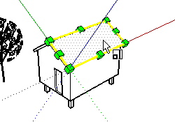
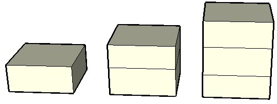
Creating a New Push/Pull Starting Face Push/Pull a face (click on the face, move, and then click again) and then press and release Ctrl (the cursor will contain a plus sign) and push/pull again. The lines that represent the edges of the top-most face will remain as the starting point for a new push/pull operation. This mechanism is useful for creating quick multilevel buildings. The following image shows a face that was pulled up (left), then the user pressed and released Ctrl and pulled again (middle) and then the user pressed and released Ctrl and pulled again (right). |

 |
|
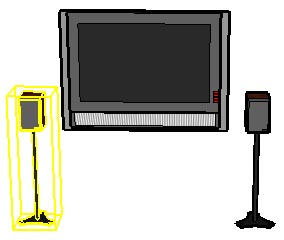
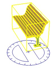
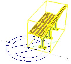
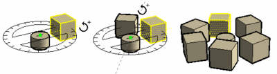
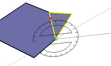
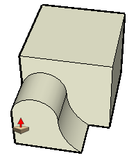
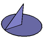
We draw an arc, then a profile (a triangle in this instance) and use the Follow me tool to sweep the profile (face) along a path. |
|
|
Click here to play a movie which shows how SketchUp the follow me tool cleverly moves a profile along a path. |
You can manually and automatically extrude a face along a path using the Follow Me Tool. Activate the Follow Me tool from the Tools menu or the Modification toolbar.
![]() Note - The path and the face must be in the same context.
Note - The path and the face must be in the same context.
Manually Extruding a Face Along a Path
The manual method for extruding a face along a path allows you to control the direction the face will travel while performing the extrude. To manually extrude a face along a path using the Follow Me tool:
-
Identify the edge of the geometry you want to modify. This edge will be your path.
-
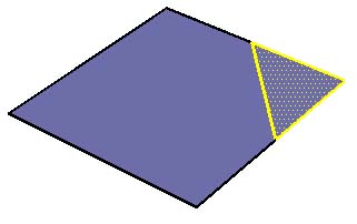
Draw a face that you want to follow the path. Make sure that this profile is approximately perpendicular to the path.
-
Click on the Follow Me tool from the toolbar. The cursor will change to a slanted cylinder with an arrow.
-
Click on the face that you created.
-
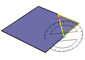
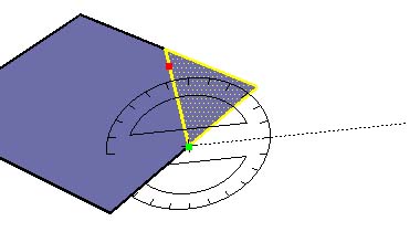
Drag the cursor along the path. SketchUp will highlight the path, in red, you are following as you drag your cursor around the model. You must touch the segment of the path immediately adjacent to the profile for the Follow Me to start in the correct location. If you select an edge, as your starting edge, that is not touching the profile, Follow Me will start extruding at that edge, not from the profile to that edge.
![]() Note - Press the Esc key at any point during the operation to start
over.
Note - Press the Esc key at any point during the operation to start
over.
-
Click to complete the Follow Me operation when you reach the end of the path.
Preselecting the Path
You can preselect the path using the select tool to help the Follow Me tool follow the correct path. To extrude a face along a pre-selected path:
-
Draw a profile of the face that you want to follow the path. Make sure that this profile is approximately perpendicular to the path.
-
Select the continuous set of edges that represent the path.
-
Select the Follow Me tool from the Tools menu (the edges should still be selected). The cursor will change to a slanted box with an arrow.
-
Click on the profile that you created. The surface will be extruded continuously along your pre-selected path.
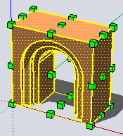
Automatically Extruding a Face Along a Single Surface Path
The simplest and most accurate way to extrude a face along a path is to have the Follow Me Tool automatically select and follow a path on a single coplaner surface. To automatically extrude a face along a path on an single surface using the Follow Me tool:
-
Identify the edge of the geometry you want to modify. This edge will be your path.
-
Draw a profile of the face that you want to follow the path. Make sure that this profile is approximately perpendicular to the path.
-
Select the Follow Me tool from the Tools menu.
-
Press and hold the Alt Key.
-
Click on the profile that you created.
-
Move the cursor off the profile surface onto the surface around which you wish to sweep. The path will automatically close.
![]() Note - If your path consists of the edges around a single surface, you
can select the surface and then the Follow Me tool to automatically
follow the edges around the surface.
Note - If your path consists of the edges around a single surface, you
can select the surface and then the Follow Me tool to automatically
follow the edges around the surface.
-
Click to commit the follow-me operation.
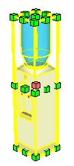
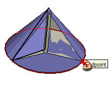
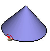
Creating a Lathed Shape
You can use the Follow Me Tool to create full lathed shapes using circular paths. To create a lathed shape:
-
Draw a circle whose edge will represent the path.
-
Draw a face perpendicular to the circle. The face does not have to be on or even touch the circle's path.
-
Select the Follow Me Tool from the Tools menu. The cursor will change to a slanted box with an arrow.
-
Follow the edge of the circle with the face using one of the methods above.
Offset
To come.
Tape measure
To come.
Protractor
To come.
Axes
To come.
Dimensions
To come.
Text
To come.
Section Plane
SketchUp allows for the creation of sections
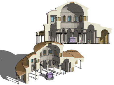
Section Cut Effects
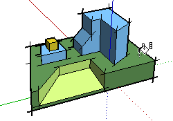
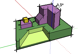
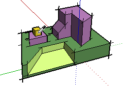
SketchUp allows you to create section cut effects which are the result of slicing through your model to see and work inside its interior. The following image shows a model of a building with a section cut affect active allowing the designer to work inside the model or present interior detail to a client.
The following model shows the section cut effect resulting from slicing through the model of a cup.
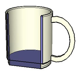
Section Planes
Section cut effects are created by section planes which are special entities used to control the selection, placement, orientation, direction, of the section slice. Section planes are generated using the Section Plane Tool.
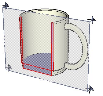
The previous image shows a section plane entity intersecting the cup and creating a section slice through the cup.
Section Slices
The term section slice refers to the edges that are highlighted after intersecting geometry with a section plane. The following image shows a section slice in red.
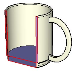
These edges act as dynamic virtual edges in that they continually change as you move the section plane through your model with the Move Tool. You can create a group from these edges, such as when slicing horizontally through a house, to create a wire frame of the model (such the outline of a floor plan). Then, export this section slice for use in a CAD program to add additional detail (such as wall construction detail).
Off road vehicle
We will use the section tool to slice through a model of an off-road vehicle.
 |
|
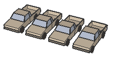
Model of an off road vehicle. |
 |
|
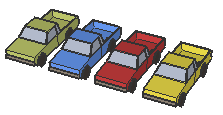
Section through the central zone of the vehicle above - metal cladding removed. |
|
|
Click here to play a movie which shows how to use the section cut tool. We cut a section through an off road vehicle. |

 SketchUp
- experimenting with display styles
SketchUp
- experimenting with display styles
Open the model OffRoadVehicle.
Use the section cut tool as shown in the movie.
Export DXF
|
|
Click here to play a movie which shows one method of exporting data from a model. |
Export STL
STL files are solid model files and can be used to export models to solid modelling software such as 3DStudio, SolidWorks, ProEngineer etc.
Review

Please review your knowledge of the material in this module before progressing to the next stage. When you have done this, return to the menu of modules.