|
Draw Commands |
|||||||||||||||||||||||||||||||||||||
|
Even though most have the tools in the Draw drop down menu have already been discussed, we think that it worthwhile revisiting them in a module dedicated to their use. Here we will cover the use of the Line, Arc, Freehand, Circle and Polygon tools. Draw drop down menu
The line tool (command)
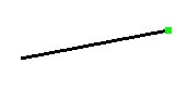
The line tool is the most basic of SketchUp commands. Select the tool, respond to the first prompt, indicate the x,y,z coordinate of the first point by clicking and then indicate the position of the end point of the line. You can draw on each of the three axes, or any point in between. Holding shift while you draw constrains a line to a face. The line is completed, the line tool stays operational, but to draw a new line from the end of the first line, you need to pick the endpoint again. This is foreign to AutoCAD and IntelliCAD users.
Closing 4 lines creates a face.
The Line Tool is more powerful than first glance would suggest. You can use it to draw edges or line entities. Lines can be joined and if closed, form a face. Once a face has been created, you can use the Line Tool to divide faces or heal deleted faces.
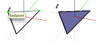
Drawing lines on a faceMake sure that you know that SketchUp expects that you draw from edge to edge. Note the entity control points at key geometric positions (end point, mid point etc.) Green is end, red is edge and mid is cyan.
Combine some arcs and lines and use the Push/Pull tool as shown in the movie.
More on lines from the Help file Keyboard Shortcut: L Drawing a Line Lines can be placed on existing faces or separate from existing geometry. To draw a Line:
The line length can be specified precisely using the VCB either before clicking the second point or immediately after the line has been drawn. See Specifying Precise Line Values for further information on using the VCB with Line entities.
Creating a Face The Line Tool will remain at the ending point of every line you create. This end point is automatically treated as a starting point for another line. You can create another line by moving the cursor and clicking again from this new starting point. These two lines are said to be coplaner, intersecting lines (intersecting at starting and ending points). Three or more coplanar lines, intersecting at their ending and starting points (forming a loop), generate a Face entity. Ensure that the Endpoint inference ToolTip is visible whenever you close a Face entity to ensure that any lines you draw are continuous. The Line Tool is released but is still active after a face has been created.
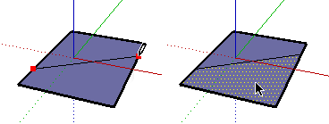
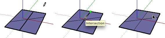
Splitting a Face Draw a line with starting and ending points on the face's edges to split a face. The following image shows a rectangle being split when a line is drawn from one edge of a face to another opposite edge.
Integrating Lines Occasionally, overlapping lines will not be split or integrate with a face. Any lines that are not part of a face perimeter will be displayed with a thicker line (left-most image below) . The Profile Edge rendering style must be enabled in the Display Settings dialog box to see this behavior. Use the Line Tool to trace along an existing line to attempt to split overlapping lines. SketchUp will re-analyze your geometry and attempt to reintegrate the line. The following images show a bold line that did not effectively split a face (left-most image). The line was traced (middle-image) and the line became thin indicating that the line was reintegrated.
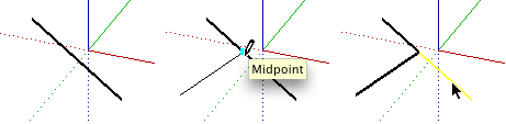
Splitting a Line SketchUp automatically splits line segments when new lines are drawn perpendicular to a line. For example, draw a new line to the midpoint (identified by a cyan square) of another line to split a line in half. The following example shows one line being intersected at the midpoint, resulting in two lines.
Select the original line to verify that the line has been split into two equal segments. Dividing a Line into Equal Segments Line segments can be divided into any number of equal line segments. To divide a line into equal segments:
Specifying Precise Line Values The VCB displays the length of your line while you are drawing lines. You can also specify an line length value using the VCB. Entering a Length Value The VCB label indicates "Length" after you place the starting point of a line. The following image shows the length value in the VCB.
Type the length into the VCB, after placing the starting point of the line, and press the Enter or Return key. SketchUp will use the current document units setting if you only type in a numerical value. You can also specify either Imperial (1’6”) or Metric (3.652m) units at any time, regardless the model units setting.
Entering a 3D Coordinate The VCB can also be used to place the end of the line at an exact coordinate in space. Entering an Absolute Coordinate: Type in the coordinates of a point in 3D space enclosed by brackets, such as [x, y, z], to get absolute coordinates relative to the current axes.
Entering a Relative Coordinate: Type the coordinate points enclosed by angle brackets, in the format <x, y, z>, where x, y, and z values are relative distances from the starting point of your line.
Drawing Lines by Inference The Line Tool uses SketchUp's sophisticated geometric inference engine to help you place your lines in 3D space. The inference decisions, made by the inference engine, are displayed in the drawing area as inference lines and inference points. These lines and points show precise alignment between the line you are drawing and the geometry of your model. Refer to the inference engine topic for additional information. Locking a Line to the Current Inference Direction Press and hold the Shift key, while the line you are drawing is the specific color of an axis, to lock drawing operation to that axis. Locking a Line to a Specific Inference Direction Press and hold either the up arrow, left arrow, or right arrow keys, where the up arrow equals blue, left arrow equals green, right arrow equals red, while drawing a line to lock the line to a specific axis. The arc commandThe arc command is a little tricky to use and benefits from some practice.
Use the rectangle tool. Select it and change its size by typing in the Value Control box (say 6000 for mm) Use the arc tool, drawing from edge to edge then setting the bulge with the last click.
The arc command (and shade sails)It is sometimes easier to draw a triangle (or other planar surface) first before using the arc command.
Follow the instructions in the movie and draw a shade sail using the arc command. Leave Google SketchUp running and return to your electronic notes. Using the polygon tool (from the Help file)
Polygons can be placed on existing faces or separate from existing geometry. To draw a polygon:
Radius and segment values can be specified using the VCB immediately after a polygon is drawn. Specifying Precise Polygon Values The VCB displays the radius after setting the center point of a polygon. Use the VCB to enter an exact radius and number of segments. Specifying a Radius The VCB's label indicates "Radius" after you place the center point of the polygon. Type the radius size in the VCB, after placing the center point, and press the Enter or Return key. You can perform this action either during or immediately following the creation of the polygon. For example: 24r or 3'6"r or 5mr. Specifying the Number of Sides The VCB's label indicates "Sides" when the Polygon Tool is initially activated. Specify the number of sides in the VCB, and press the Enter or Return key, before clicking to set the center point of the polygon. For example: 10. You can also specify the number of sides in a polygon immediately after the creation of the polygon. Type the number of sides in the VCB, followed by the letter 's', and press the Enter or Return key. For example: 6s. This number will be applied to any future polygons. Locking a Polygon to its Current Orientation Press and hold the Shift key, before you begin drawing a polygon, to lock drawing operation to that orientation. More on Polygons SketchUp's Polygon entities are similar to Faces entities, but can have 3 or more sides. These entities act as a single line in that they can define the edge of a face and also divide a face. Additionally, selecting one segment of the polygon selects the entire Polygon entity. However, all inference techniques will operate on the Polygon as though it were comprised of segments.
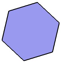
Polygon entities are comprised of a radius and number of segments. The following image shows a six-sided polygon.
Editing a Polygon Entity You can edit the radius of a circle in which the polygon is inscribed, that does not yet bound a face, by using the Move Tool. To edit a Polygon entity:
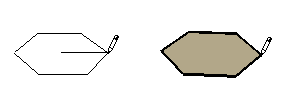
You can also adjust the radius and number of segments using the Polygon entity's Entity Info dialog box. Editing an Extruded Polygon When you use the Push/Pull Tool to extrude a 2D face that includes a polygon, it extrudes a special polygonal curved face set which can also have its radius edited. Use the Move Tool to reposition one of the control edges, and the polygonal curved face set radius (as well as the radii of the two polygon entities that define it) will be adjusted accordingly. Polygon Deformation If a polygon is deformed in a way that destroys its radial definition, such as with a non-uniform scale operation, it will become a non-parametric Polyline Curve. Polyline Curves can no longer be edited as polygons. FreehandThe Freehand tool draws curves on existing faces (or on axes). We find that this tool is very difficult to control and places rather too many entities into the drawing. We believe that flexible curves are best drawn as Bezier curves. The curve in the model below was drawn in CAD software (IntelliCAD) and then imported into the SketchUp environment.
To apply these in the SketchUp environment, it is necessary to load what is called a Ruby scrip. More on that in a later module. To draw a curve:
RectangleLet's take another look at the rectangle tool.
CircleWe have already experimented enough with this tool. That completes a further look at the various draw commands. Review
Please review your knowledge of the material in this module before progressing to the next stage. When you have done this, return to the menu of modules. |

 SketchUp
- the arc command
SketchUp
- the arc command