|
Case Study - Archer Interiors design |
||||||||||||||||||||||||||||||||||||||||||||||||||||||||||
|
There are times when it is useful to use a plan from CAD software as a base for developing your SketchUp model. In this example, we will imagine that we had received a plan from and architect who was using AutoCAD or IntelliCAD and we wanted to build a model of a kitchen to show a concept design to a client. Working in this way can save you time, as you do not have to create the geometry from scratch. We will produce a model similar to that shown below.
Preliminary stepsIt is important to know your CAD drawing before you start. If you are organized in the CAD environment and follow good drafting practice - using named text styles, named dimension styles, appropriately named layers to separate logical parts of the design, blocks to minimize file size and tools such as IntelliCAD's Verify or the AutoCAD standards management tool etc. to build a well constructed drawing, then you will be able to work efficiently in the SketchUp environment with the 2-D plan as a base.
To sum up, cut out the part of the main drawing you want to use with the WBLOCK command, make the 2-D file as small as possible, purge and AUDIT the drawing. Check on layer use and naming conventions, write out a DXF file - we use AutoCAD Release 14 ASCII DXF format. Print the drawing out so that you have something to refer to while working in SketchUp. The figures below show steps in the process.
Note that AutoCAD does not allow the same range of export options as IntelliCAD, nor does it distinuish between Binary and DXF files. The safe option if you are using AutoCAD is to use the r12/LT2 DXF option. It is a true ASCII file.
Start SketchUpAs a first step, you want to bring your 2-D CAD drawing into SketchUp via DXF.
To sum up:
Note that linetypes used in the CAD program do not import correctly into SketchUp.
The figure below shows the same area in SketchUp
We are now ready to start work. Draw internal walls Use the line tool to trace over the lines of internal walls.
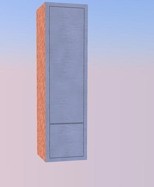
Pantry cupboard unit sets Next the designer tells us that she wants three pantry cupboard sets along the wall. The figure below shows the type of unit. To create this effect, we can simply draw a box and attach materials to the front surface.
Make a new layer (perhaps called SKP-PantryUnits). Set that layer as current. Draw four lines representing the base of the cupboard and pull up to 2150 high. [The cupboard unit is 600 wide, but that is dictated by the base plan.]
It would be possible to attach materials and put some ornamentation on the surface of the front panel of the unit (see below). As mentioned in the movie, we prefer to keep things simple. Adding more information can come later. The figure below shows a rendered unit in SketchUp (top) where we have added some ornamentation and the same cupboard in an external renderer (bottom).
Make component The next logical step is to make a component of this unit and copy it (there are 3 pantry units in the plan). The make component tool is reached via the Edit drop down menu.
Copy the component Now we copy the unit three times to make a wall of pantry cabinets.
Bench top Once these initial components are in place, the model builds quickly in complexity.
We needed to make some adjustment to the positioning of the bench and add some other spaces for items such as Meile Steam Oven, Meile wall oven, Meile microwave etc. Meile wall oven We have a pre-made component from the warehouse.
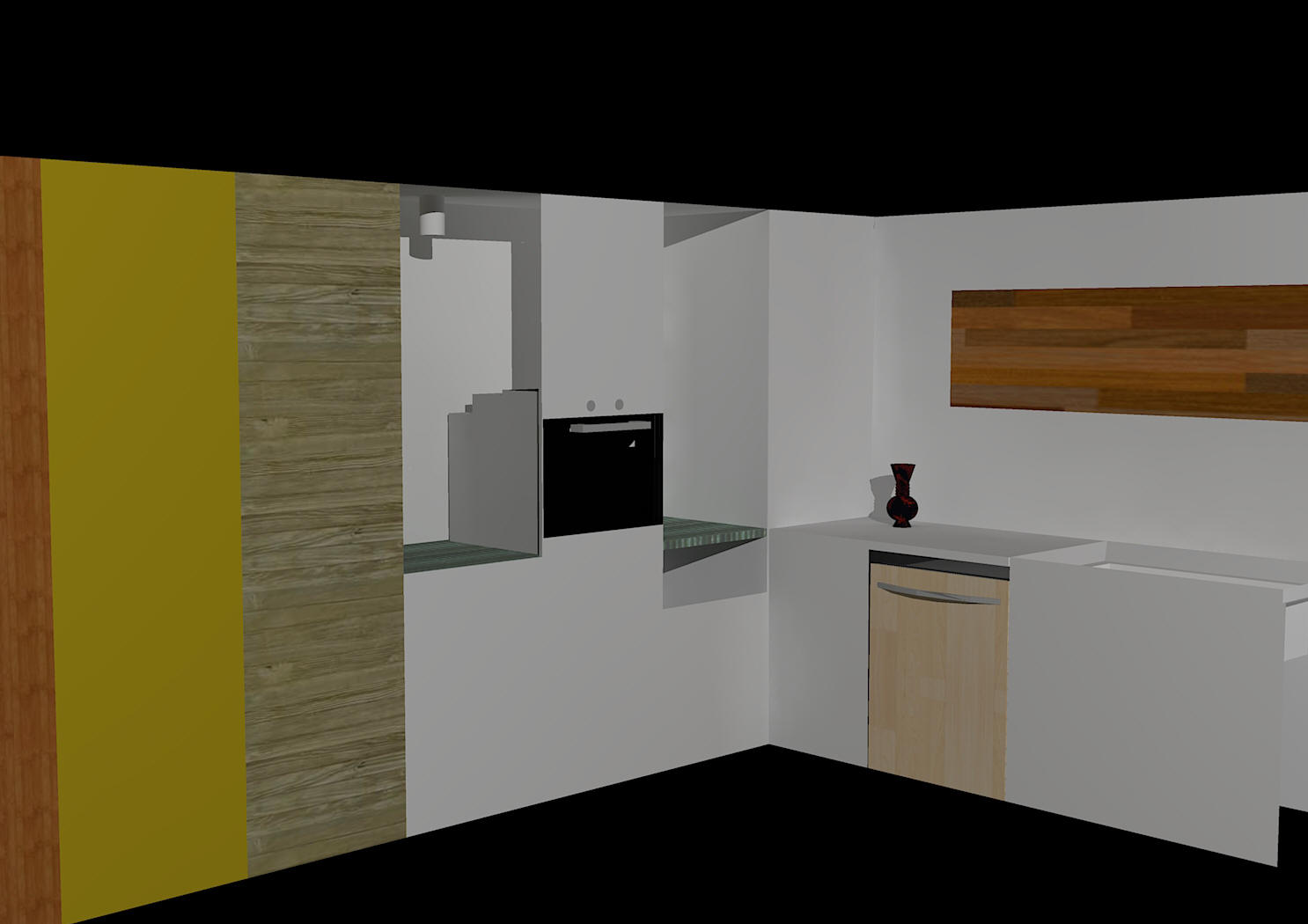
We continue to work our way around the corner of the space, adding components as required. In the figure below, we have associated some materials with surfaces - the view is rendered.
We continue to 'tweak' the design, adding images to the wall hangings.
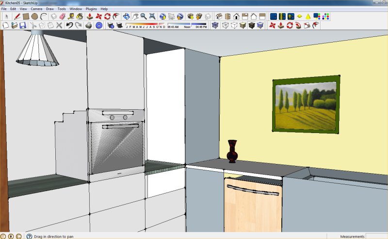
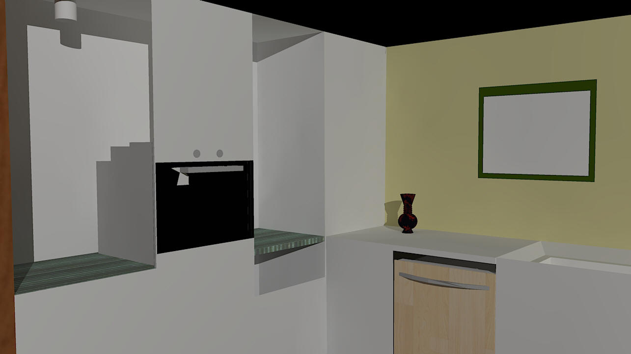
Improve rendering inside SketchUp (Podium) Podium is a rendering tool which can be 'plugged in' to the SketchUp environment. The figure below shows the result using the free version of Podium which allows rendering up to 500 pixels wide.
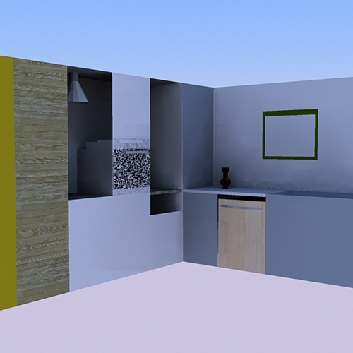
Render outside of SketchUp There are a large number of software tools [3D studio, Kerkythera, Renderman,] which can accept data about your model (export from SketchUp) and render your model.
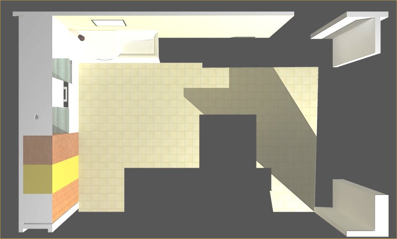
Don't forget that a rendered top view can be a very effective method of conveying your design ideas.
Clearly the results differ markedly from renderer to renderer. For many purposes, rendering in SketchUp is more than adequate to show your design ideas.
Please review your knowledge of the material in this module tutor before progressing to the next module. |